I have often thought of buying a smaller twin belt sander/grinder thinking they would be very useful around the shop. Most manufacturers offer a small 30" belt and 6" disk sander but I find the disk pretty useless and better left to larger disk machines. For twin belt machines there are large units available, such as the one pictured below, but they are expensive and designed for heavy metal removal. Something more suited to finishing small wood and metal parts and cleaning and touching up many of the tools used around the shop is more what I had in mind.
I decided on a plan that utilized the ideas of George Barnes who made a set of plans for a larger 2" X 42" single belt sander and made them freely available.42" belts are hard to source so some builders there have modified the plans for 48" belts.
I decided this would be a good casting project. I redesigned the tension and tilt assembly based on the same principle as Mr. Barnes plan but more suited to the materials I had on hand. And of course dimensions were much smaller for 30" belts. Below is my actual size sketch plan, a similar sketch was cut out as a template to cut the frames in plywood.
In a little side bar here. A similar project I want to do sometime is a 1" X 48" sander/grinder that will do internal sanding and grinding, similar to the machine pictured below. It would of course be a double belt design, mounted on a larger 8" grinder motor assembly.
So to get started on this project. An importer of cheap shop tools had a going out of business sale in my area a number of years ago. I picked up 5 of each 6" and 8" grinders for a song, they are not much good as grinders, underpowered and vibrate too much, but as small double shaft motors they were cheap. I will go with the 6" grinder motor for this project, its labeled ½ HP but is actually closer to ¼ HP.
The plywood frames for the pattern cut out.
Next I traced the frames on to 2-¾" X 5 ½" X 16" clear pine and cut them out. Next I centered and marked out the collar cut outs. Below I am cutting out the collar openings.
In the next picture I am cutting out the center to form the frame ribs.
All cut out and trying out the fit. The bottom wheels pictured are from a dead 3 X 21 belt sander I still had the parts kicking around from. If they don't last I'll cast and turn up a aluminum set later.
The glue-up, clamped overnight.
After glue-up.
Next all edges are rounded except the plywood edge at the parting line, in the rounding, draft is also sanded into the sides to insure a clean release from the mold. ¾" doweling is sawed in half and glued to top of frame. The tilt/tension mechanism will be mounted here.
All inside edges are rounded off with bondo body filler and allowed to dry.
Here 2 coats of durathane have been applied to finish and seal the pattern.
So we are ready to mold, but first I have to build a quick set of larger flasks the two I have are to small. Again winter is coming so these are cheap and quick to get the job done. I am using 1 X 4 strapping glued and drywall screwed. Handles and alignment pins quickly cut and attached from plywood.
The drag rolled over. The pouring and riser sprues are then placed, more parting dust and the cope section is placed and rammed up.

Mold opened up and pattern removed.
The pouring and riser channels cut, ready to close up and pour.
Not safe to pour on concrete but, here we are. The two main doors to the garage/workshop were opened creating a good cross draft through the shop.
The melt almost ready. I should say a word here about the "Hothead" furnace performance, it has continued to operate like a champ, quick melts and trouble free operation.
Proceeds of the melt.
All shook out and ready to trim and clean up.
Sprues and channels cut off and cleaned up with file and wire wheel.
Another little side bar here. Below is one of the 8" cheap bench grinders I mentioned earlier, I modified the guards and converted it to a powered wire wheel, Its great for cleaning up painted or rusted surfaces and can't be beat for cleaning up aluminum castings. The red strap bolted to both guards is to keep vibration in the guards to a minimum.
After a good session of sanding and grinding, I completed the collar opening with a slight taper for a snug friction fit on the motor housing.
Next I started with the upper wheels. I sawed 1 ½" long rounds off a piece of 1 ¾" round aluminum bar I had in my junk boxes.
Next I faced, crowned and bored bearing seats on my mini-lathe.
The bearings were a nice press fit.
I had shoulder bolts but the wrong size for the bearings, So I turned them down to fit.
The completed upper wheels.
The tilt mechanism was cut from a nice piece of bar stock I had. I didn't like the idea of welded pipe as used in G. Barnes plans.
Two views of the assembled mechanism.
And here they are installed on the frame castings.
The castings are mounted to the motor housing with a friction fit and tightened with the three screws that would normally mount the grinder guards.
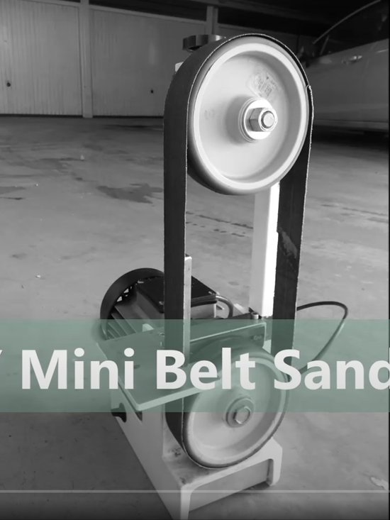
Here the bottom wheels and a couple of belts are installed. Ready to try.
You can't tell but the sander is running in this picture. Very smooth with no vibration as evidenced by the rod standing on its end.
I took a couple of days thinking about the mounting of the belt backing plate and different tool rest options, this is what I came up with. Everything is mounted with wing nuts, making it easy to adjust or change the different tool rests. Parts were all sourced and modified from my junk box collections.
So thats it we are finished. Here are the centerfold pictures in all its different outfits.
I built this back in November, since then it has proved as useful as I had envisioned. Rarely a day goes by in the shop that I don't use it. It has lots of power in this configuration and is great for shaping and finishing small wood and metal parts. It is great for cleaning, touching up and sharpening common shop tools like punches, chisels, drill bits and any other tools that require these operations.
And best of all cost $15 for the grinder and $2 for the easily sourced belts.


Ask Me Anything